

Why we don’t automate CAM programming

Theo Saville
April 2, 2026

Will robots take my CNC job?
CloudNC
March 24, 2026

How to Solve the CNC Machinist Shortage in 2026: The AI Approach
Norval Scott
March 18, 2026
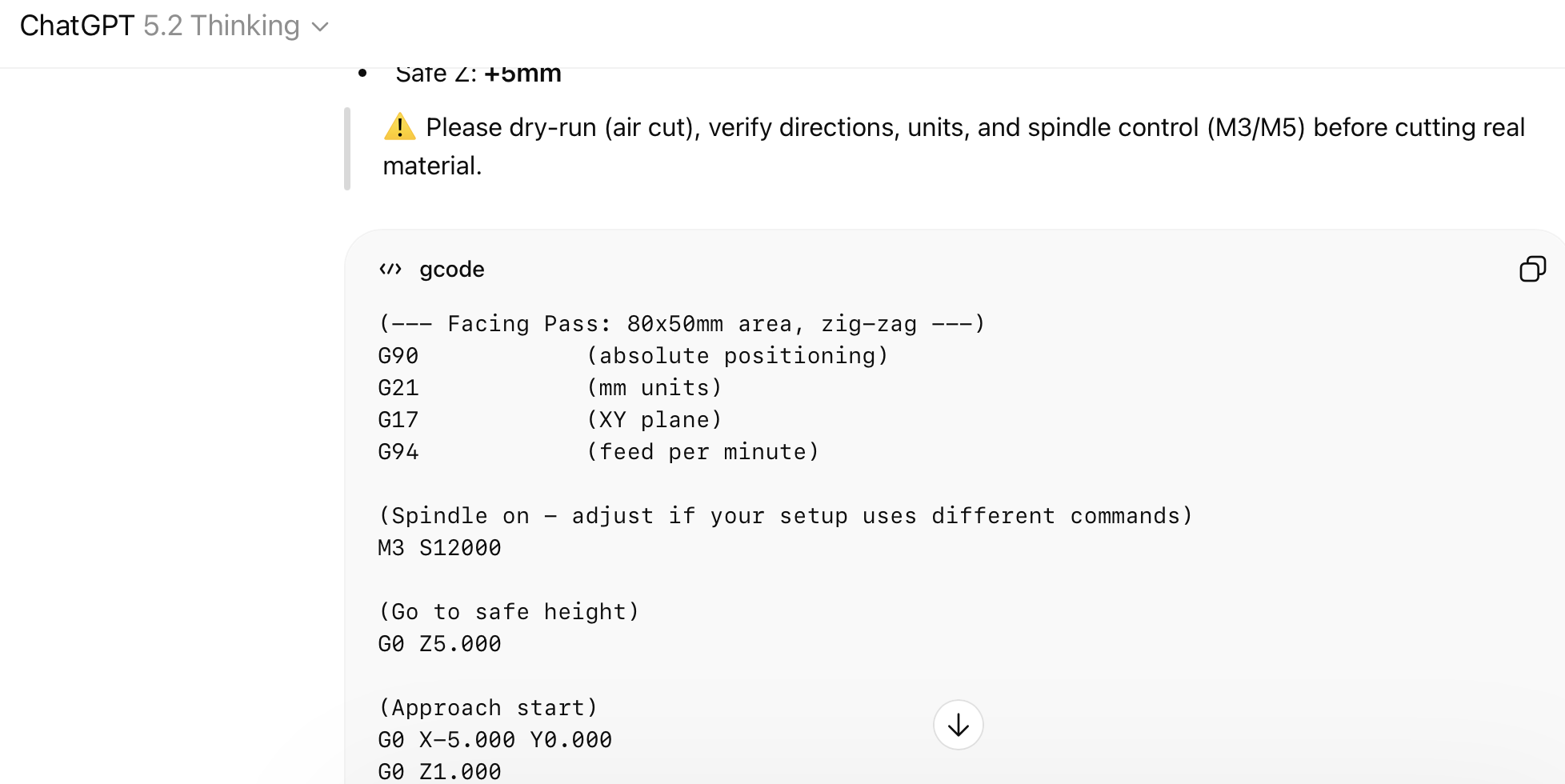
Can I use ChatGPT for generating G-code?
CloudNC
March 4, 2026
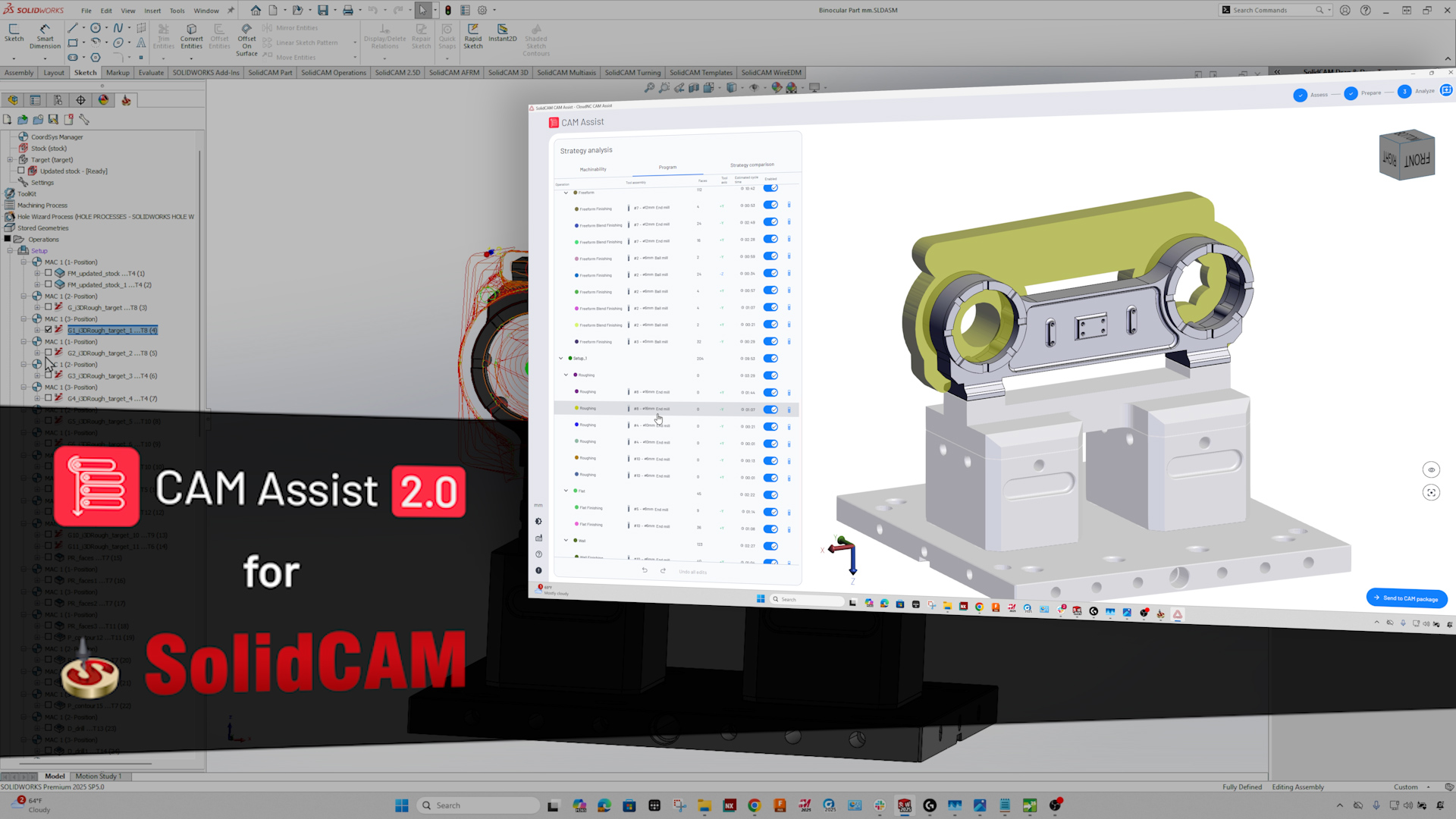
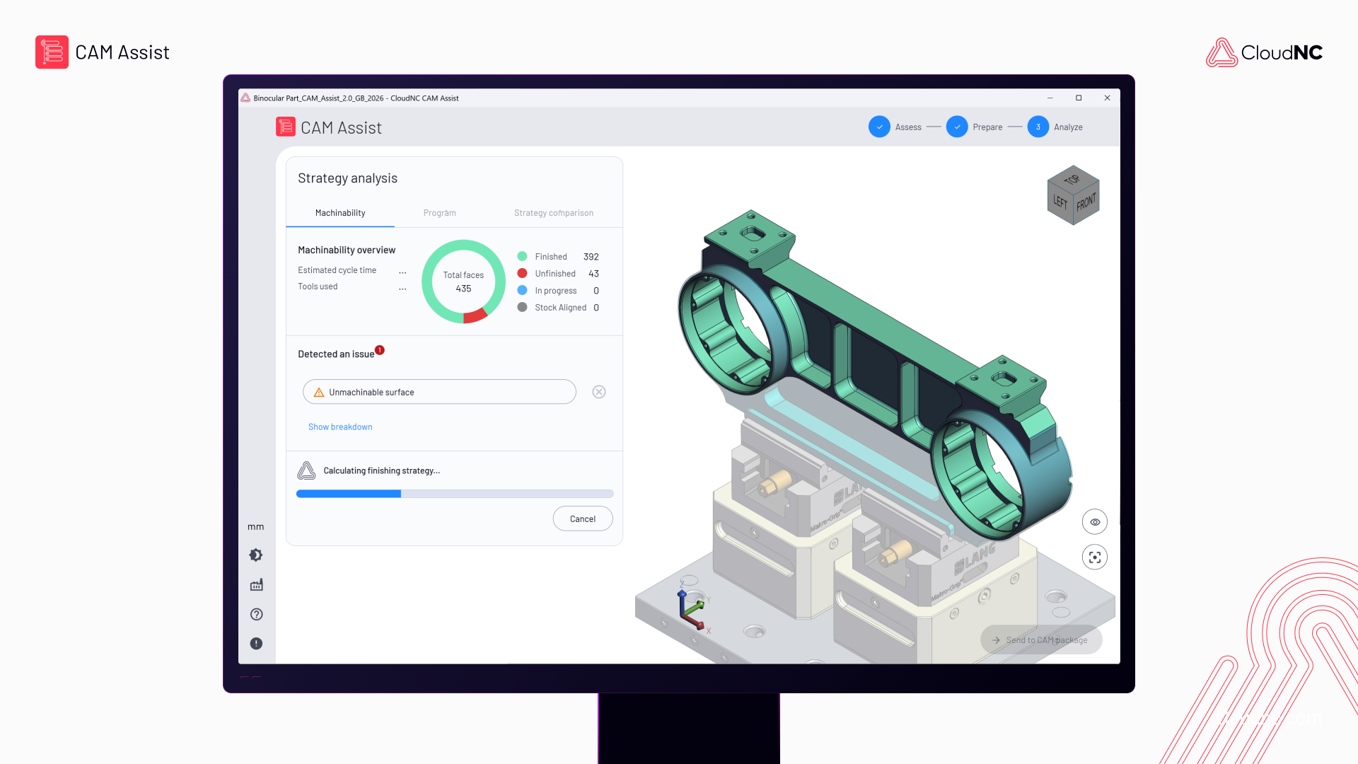
CAM Assist for SolidCAM: now in early access!
CloudNC
February 20, 2026
How to start your own CNC machine shop
CloudNC
February 10, 2026

When metal stops being the bottleneck
Theo Saville
January 30, 2026

How to lower tooling costs in CNC
CloudNC
January 27, 2026

How to become an advanced machinist quickly
CloudNC
January 13, 2026
Practical Machinist: 2.0 Deep Dive
CloudNC
December 12, 2025
How to manage cash flow in machining
Jason Bowes
December 12, 2025
7 Ways to Get Faster at CAM Programming
CloudNC
November 27, 2025