What are near net-shape parts?
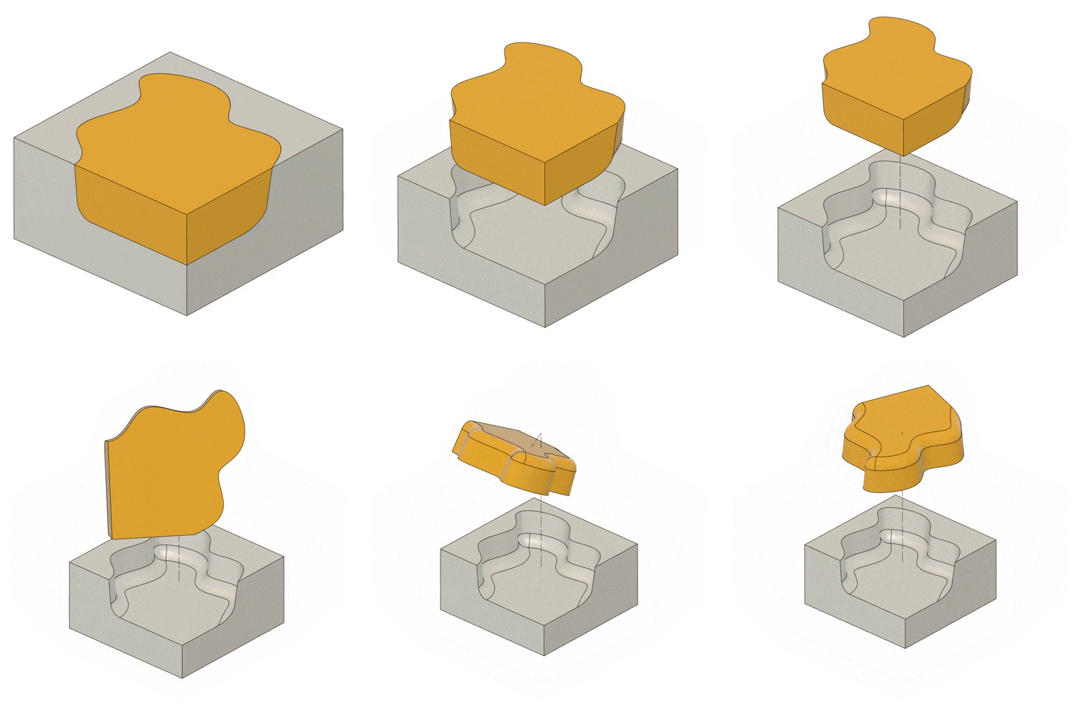
For CNC machining, we have two raw material options: forged billet stock or a near net-shape (NNS).
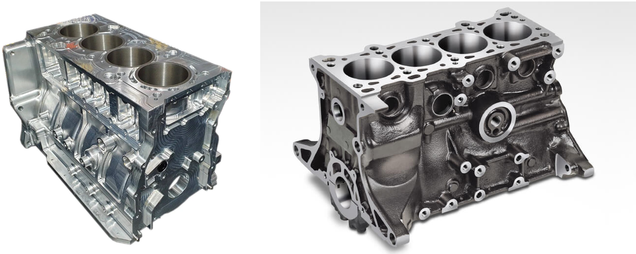
Machining from billet stock gives us the benefits of excellent material properties and consistent quality. The level of flexibility and low investment in tooling can also make billets the better option, particularly for low batch sizes and small parts. However, billet can become more expensive than NNS if a high volume of material needs to be removed across huge numbers of units (in some cases the mass of swarf can be higher than the mass of your finished product).
In this case, it may make sense to introduce a NNS process prior to milling. This uses a material which has already been processed into a size and shape that is close to the final required geometry which can then be more efficiently and cost-effectively finished in the CNC machine. There are many methods to produce the NNS including hot & cold forging, sand & die casting, fabrication, lasercutting and water jet cutting – the requirements of the design and project will determine which method is used.
Machined features will be designed differently, depending on which near net-shape manufacturing process we select. We must have a fully concurrent approach to design, simultaneously considering the design requirements, forming process requirements, and CNC machining requirements.
When to use a near net-shape?
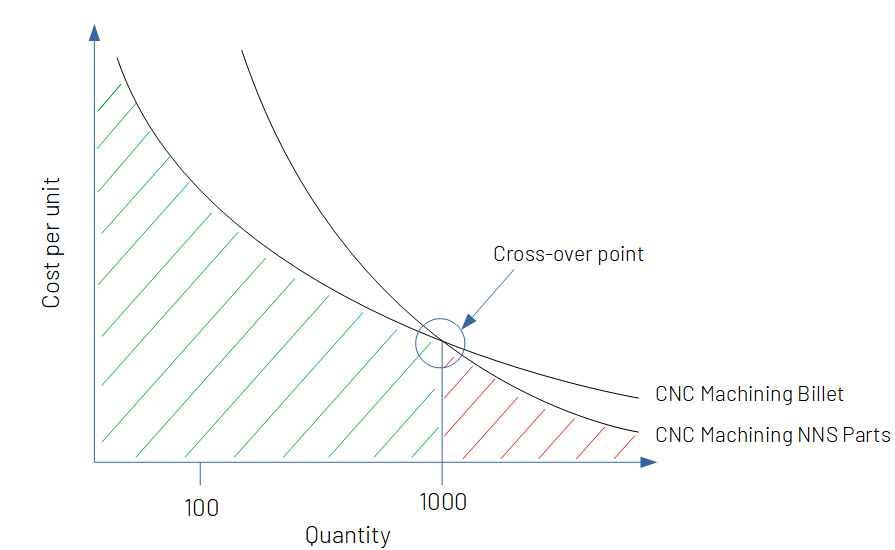
The primary reason is cost reduction for high volumes. Machining of near net-shape parts usually requires a very large up-front investment in moulds and tooling. This initial NNS investment won’t change whether we’re making 1 unit or 1000, so it is more economically viable to spread the up-front investment over a larger volume production. Conversely, CNC machining of billet material has a very low initial investment for low volume production and is very well suited to prototyping and small to medium production runs (<1,000 parts). As production volume increases for a given project, there is a cross-over point where machining of near net-shape parts is more cost effective than machining billet, over the life of the project.
Design Considerations for near net-shape
Unmilled surfaces in final product
In some circumstances it is acceptable to not machine all surfaces, which can offer opportunity for significant cost savings. First, you should understand the tolerances achievable with the selected process. Dimensional stability & surface finish of a moulding process will be far worse than what would be achieved by CNC machining (even roughing). For example a sand cast surface finish is typically >15Ra, compared with <3.2Ra achievable with milling.
If the feature demands a high level of dimensional stability or if the tolerances required can not be achieved in the forming process, then it should be designed as a milled feature.
Adding machining allowance
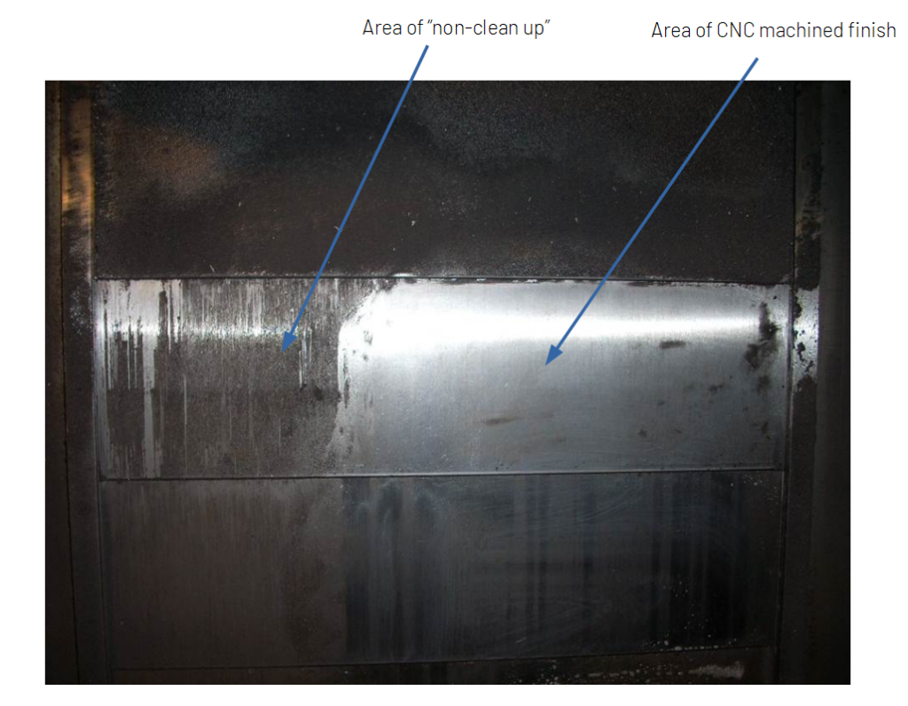
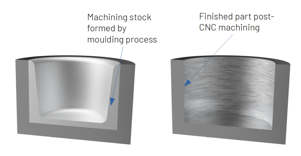
Machining allowance or “stock” is additional material created as part of the forming process which is subsequently removed by CNC machining. There can be a high level of dimensional variation in forming processes; the moulded part could be up to a few millimetres smaller than your designed geometry which could cause us big problems when CNC machining.
If a moulded face has moved significantly, the cutting tool might not make contact at all with the moulded part. The result is an un-machined or partly-machined face where we were expecting a high-quality CNC machined face. This partly machined condition is referred to as “non-clean up”.
We must ensure that the CNC machine always makes the cut we require, so additional material is designed in and machined back to the required form.
Understand minimum wall thicknesses
Forming processes are often limited to a minimum and maximum wall thickness. If wall thicknesses are too thin, material will cool and solidify before flowing fully into the mould cavity, causing defects. If wall thicknesses are too high, shrinkage defects could occur. The moulding supplier will have their own recommendations on minimum wall thicknesses. We also recommend not machining a wall-less than 3mm thick.
There are often high forces when machining a part, and a thin wall will not be able to support those forces resulting in damage to the workpiece and/or the machining tool. Machining very thin walls (<3mm) is possible but slower and thereby more expensive, and should be avoided when possible.
Specify allowable defects
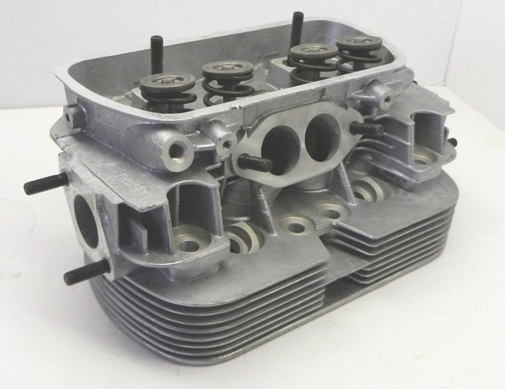
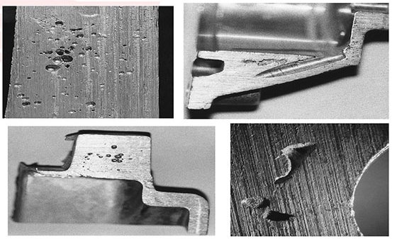
All formed parts will have some level of defect in them. Zero defect parts are almost impossible to achieve. We recommend communicating to your supplier where on your design defects would be catastrophic, and where they would be acceptable. For example, a 3mm bubble of shrinkage porosity in a cast cooling rib of an air-cooled cylinder head might not be a problem, but the same defect in the 3mm wall between a cylinder and water jacket of a water-cooled engine would be a bigger problem.
Design clearance cuts
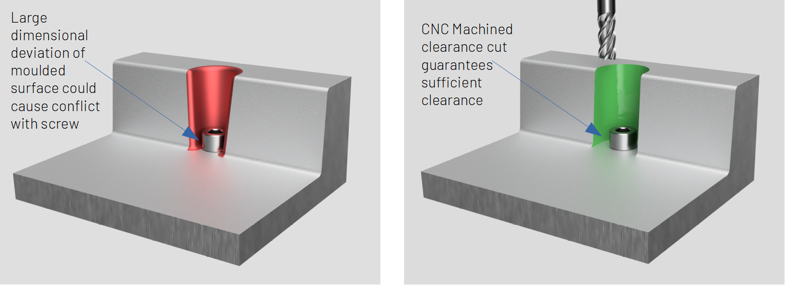
Features created by forming processes will have a high level of dimension variation. A sand cast part 250mm long could deviate in length up to 2.2mm from nominal designed geometry. We need to consider this when designing. If movement of a formed surface by a few millimetres would cause failure of your part, then we recommended adding a clearance cut as a CNC machined feature. This ensures that the part functions as required, every time.
Non-Homogenous material properties
Forming processes often have their own specific materials, which will likely have lower material properties than their billet equivalent. Bear this in mind and use process-specific material specifications when performing calculations or Finite Element Analysis. Material properties are often not homogenous through a manufactured part. For example in cast parts, metal which has cooled and solidified very slowly can have very low yield strength, sometimes less than the quoted material data. Your supplier should be able to give you data specific to their material and process, which you can use in the design process.
Define raw part datums
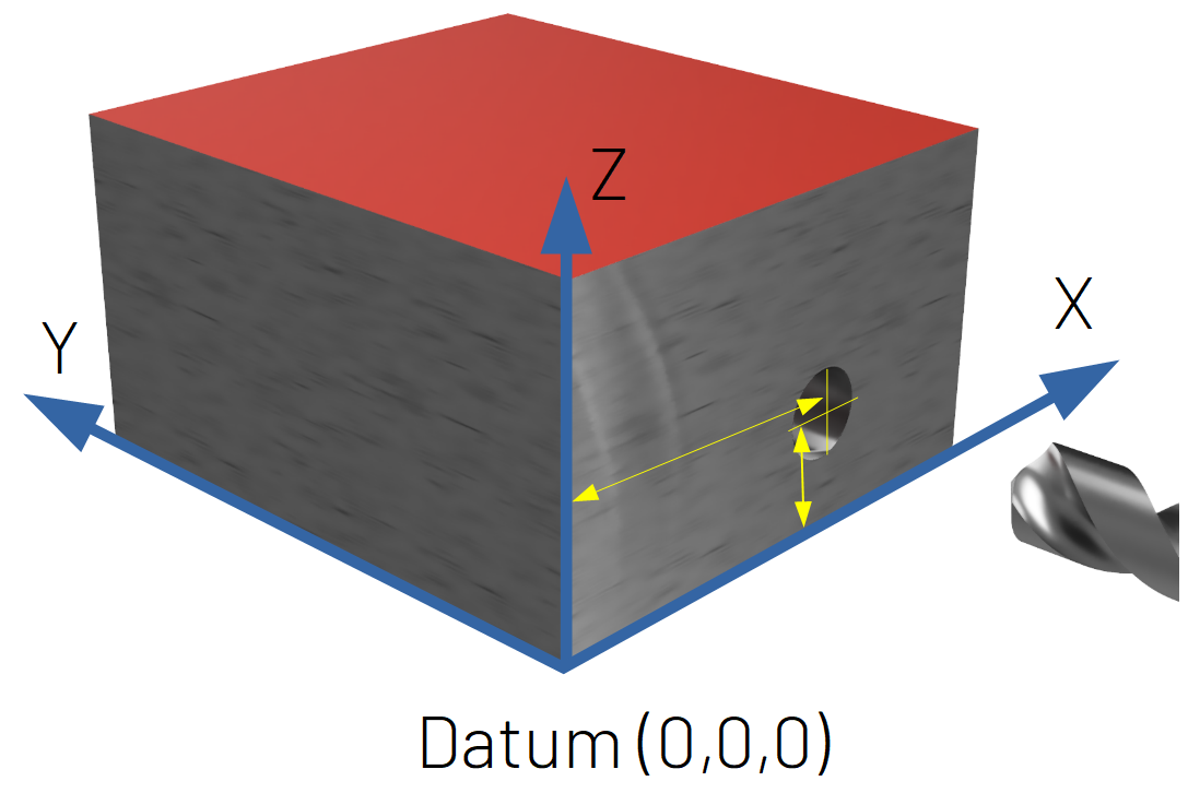
“Datums” are used in CNC machining to create a ZERO position. All other machined features are created relative to this datum, so in the case of the hole below, we know where on the front face it needs to be on the part based on it’s X and Z distance from the datum, and depth based on the Z datum. Typically a CNC machine creates this datum by machining 3 flat faces. This often does not take into account the shape of the raw moulded geometry.
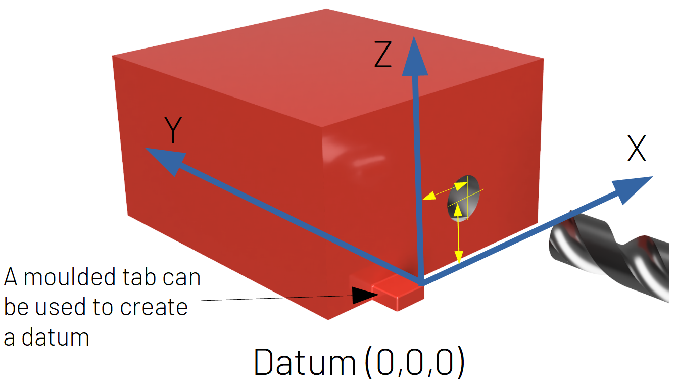
Understanding the shape of the raw formed part is important when CNC machining. It will be slightly different to your designed geometry, due to process variation. We can measure the geometry of each raw part using various metrology techniques, however, this can be expensive and time-consuming. A better solution is to design datums created as part of the forming process and are not subsequently machined. The CNC machine can then pick-up on these datums, and begin machining very quickly, without need for measurement.
Consider corner radii
Forming and moulding processes will almost always require minimum radii. Sharp corners in moulded parts are not favourable for two reasons. Firstly, many moulding processes use heat to form the part, and sharp corners encourage high-intensity focussing of this heat, resulting in potential defects. Secondly, if the mould is a negative impression of the required geometry (for example in die casting), an internal radius on the part is formed by an external radius on the die. A sharp corner on a die is likely to get worn down with use, and a natural uncontrolled radius is likely to form of its own accord. We would recommend discussing with your supplier their minimum required corner radii. If a corner radius is not acceptable in your design, designing the feature as a CNC machined operation might be more suitable.

Design in draft angles
Draft angles are often required in a design to remove the part from the mould or die. Your near net-shape supplier can advise you on their minimum required draft angles for manufacture. If your design cannot accommodate a drafted wall, you can finish the feature with a machining process.
Machining of near net-shape parts is a great way to reduce the cost of your product. Design using our best practices to ensure your CloudNC machined part is of the highest quality, and get in touch with our expert Design for Manufacturing team to discuss your project if you are unsure!


%201-p-1600.png)

