.png)
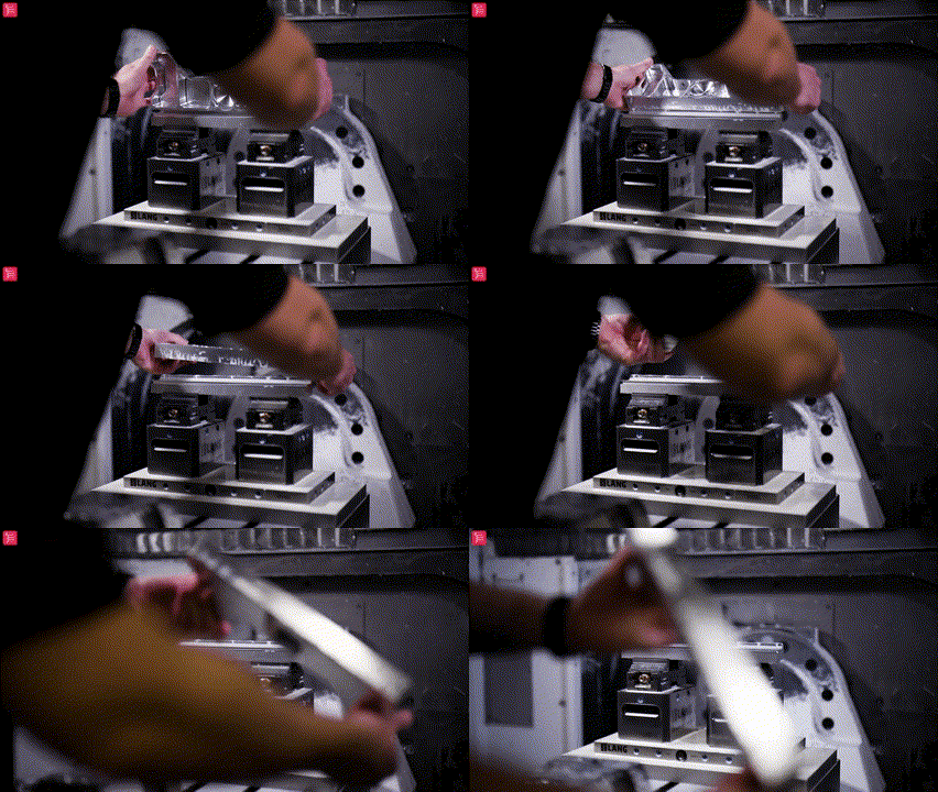
At CloudNC, our main ambition is to streamline the precision part CNC manufacturing process wherever possible. This can range from standardizing our machine tooling, to using our groundbreaking AI technology to generate our machine tool path, and everything in-between.
One critical area where the manufacturing process can be optimized is the machining methodology: i.e., the orientation of how the part is held, how many operations, and the order in which the material is removed.
Designing a method to break out a component in one single manufacturing operation - using a 5-axis CNC machine - can be one of the most cost-effective ways to get a part out to a customer within minimal lead time. Using this method machinists can expect to achieve reduced setup time and scrap, all whilst improving part accuracy… well, at least in most cases. Like any subject in machining, there are exceptions!
So why should I consider breaking my part out in one single operation?
- Reduces CAD/CAM lead time - Eliminates the need for fixtures, reducing CAD design and CNC manufacturing lead time. Some parts include complex freeform geometries that can make holding for the second operation difficult: this is another advantage to making the need for fixturing redundant.
- Reduces machine setup time - The billet is held in a vice on a 5-axis machine, for 3+2 operations, all material is removed until the complete part is held only by tabs, therefore no need to change over the workholding setup on the machine for a proceeding operation.
- Reduces the risk of part scrap - Eliminating the need for proceeding machining operations automatically reduces the risk of machine setting error, i.e. datum and tool setting, subsequently reducing the risk of scrapping the part.
- Reduces time spent in Quality - When the part is completed in one operation, only one final check of the part is required, eliminating the need for several stage checks.
- Improves part accuracy - When machining a part in one operation, all of the geometrical features are machined relative to each other (i.e. - not completed between different setups). Providing that the machine kinematics are calibrated, this can improve the positional accuracy between critical part features. The one caveat here is how likely the material is to distort during the machining process.
Sounds good, so when should I be using this break-out manufacturing process?
So first of all, this process is completely part dependent, and it’s critical that at least one side of the part has only a face with no other features - i.e. a ‘spare’ side.
When you have a 3+2 orientated part with one spare side, you then need to be able to hold the part in such an orientation that you can access all the remaining features on the part, whilst avoiding the vice when machining using 3+2 indexing. Make no mistake about it - some parts are totally impossible to machine in one single operation.
For me, the single operation break-out method is ideal for prototype/low quantity production, as the aim here is getting the part running on the machine, and then off to the customer within minimal turnaround time.
To do this I utilize my standard machine datum and standard vice setup on the 5-axis machine, this setup is also modeled by default in my CAM software. I then:
- Import the part model
- Create the tab geometry (a task that can take up to an hour)
- Program the single operation (utilizing standard tooling where possible)
- Run the program on the 5-axis machine, thereby completing the part in one operation
The efficiency here comes from the single process steps, i.e.:
- Design
- Program
- Machine
- Quality assurance check.
If, for example, I was to make the same part with two operations and one fixture, I would then repeat these process steps at least three times over - effectively tripling the lead time to manufacture the part.
So when should I avoid breaking my part out in one operation?
The obvious answer here is when you have a part that has features on all sides, and therefore is impossible to complete in one machining operation. Apart from this, there are a few other things to consider…
One of the biggest obstacles you will face when breaking a part out in operation is material distortion, as once the part is snapped out, “You get what you get!”
This means parts with tight flatness/positional tolerances may be affected if the material is likely to distort. My rule of thumb here is if these limits are tighter than 0.1mm, the break-out process may not be the best method to use. Retrospectively, if the part is larger (for example, it needs to be held across two vices), the effect of distortion will be amplified, which may require even more generous limits.
If you are worried about material distortion, but still want to break the part out in one operation, you can take precautions such as skimming the skin off of the billet first, and possibly adding a machine stop (M00) to release and re-nip before finishing.
However, you do need to understand that these are only precautions, and will not guarantee the part does not distort on break-out. If material distortion is a real concern, it is advisable to stick to a multi-operation machining method where the parts can be stress relieved before finishing.
Is the single operation break-out method ideal for high volume production?
Short answer - No! There are two main reasons for this:
1) Any method you design to break a part out in one single operation will leave either one face of the part that needs to be hand polished, or one edge that needs to be hand deburred (and, in some cases, both).
On high volume production runs, hand deburring or hand polishing is to be avoided to maintain process efficiency and part quality. The part should be 100% machine finished and deburred. Technically you could finish on the machine, and debur the remaining face in a second operation, but for me, you either snap a part out in one operation or you don’t… i.e. if you need to set up a second operation just stick to a more traditional multi-operation machining process.
2) Snapping out a part in one operation can have a negative effect on cycle time efficiency. When holding the part upright in a position/orientation, allowing you to gain access to all the features in one operation typically means that at some point the part will become unstable. To get around this, you need to methodically rough and finish the part in stages, leaving features rigid until the last possible minute.
This process of “Gentle” material removal often leads to increased cycle time. For high volume production parts, it can be more efficient to machine the part between various operations where the part can be held in multiple secure setups, allowing for better material removal rates, and therefore a combined (between operations) reduced cycle time for the part.
There are two variations of methods that can be used when breaking a part out in one operation:
Traditional tag method:
Video: A - Triangular tag formation
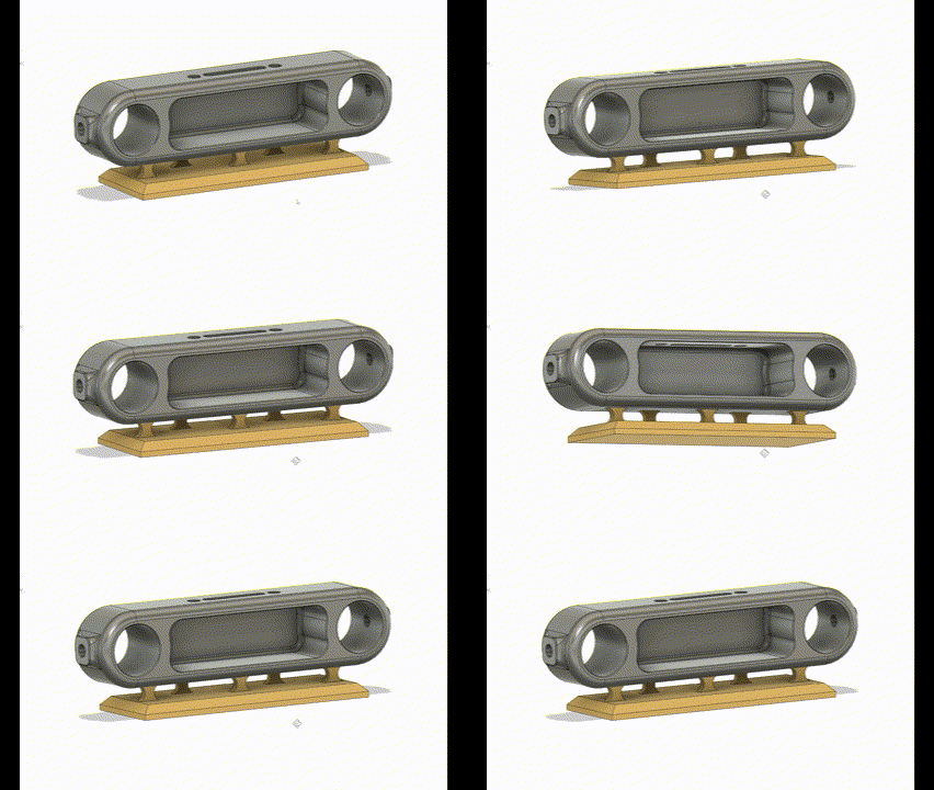
Traditional tags are the most common way to hold a part to a machine complete in one operation. Each tag joins to a surface, or surfaces, of the part.
In some occasions this tag design can be incorporated into a frame around the outside of the part: this is when the part you are machining is likely to flex, and tags are needed to support the part from various directions until the part is complete and ready to be snapped out.
In the example above (Video A) the part is fairly rigid, meaning tags solely on the bottom face are sufficient. You will notice that the tags are laid out in a triangular formation, i.e. two closer to the front, with the central one closer to the back of the part. This is purposely done for two reasons:
- The triangular footprint of the tags provides a wider, more rigid hold of the part, i.e. if all tags were inline, the part would be prone to vibration as only the central axis (Thru X in this case) would be sufficiently supported.
- As shown in the example below (Video B) the triangular formation creates small pockets in between the tags at the front and back of the part, which are offset to each other. When it comes to finishing the back face of the part, the machine bed can index over to 90 degrees (Around A axis in this case), allowing an endmill to pocket finish between the tags, with the bottom of the tool going past the centerline of the face. The part then rotates 180 degrees (Around the C axis in this case) to repeat the process on the opposite side. This allows the majority of the back face to be machine finished, excluding only where the individual tag geometry is.
Video: B - Pocket finishing between tags to finish back face
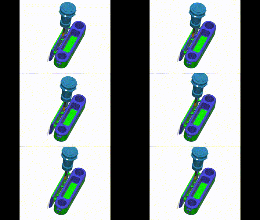
Note: Consider the diameter of the endmill you want to use to finish the back face when you design the pocket/tag geometry, as pocket width will dictate the maximum diameter of endmill that can be used.
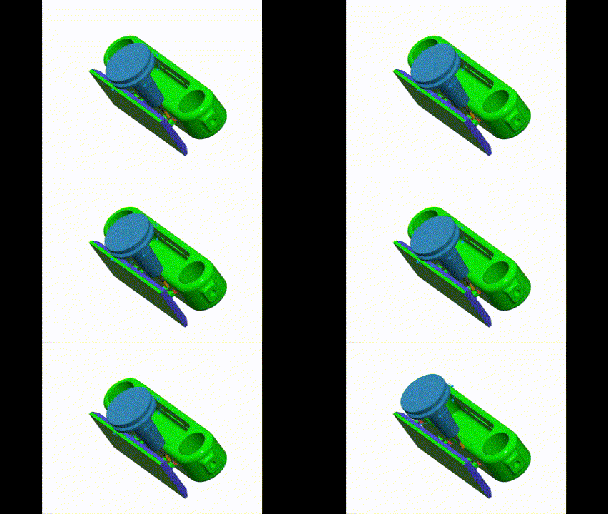
My preferred method when designing these tags is to model them thick (5mm in this case). This creates a rigid hold of the part, allowing me to get a good material removal rate when roughing the excess material away. When the part is machined complete and ready to be snapped off, I simply bring out a small endmill and gradually reduce a section of each tag thickness to approx 0.5mm, as demonstrated below in Video C. (Final Tag thickness can vary depending on size of part, how many tags there are, etc…)
Video: C - Using small diameter endmill to reduce tag thickness for break-off
For more information on using traditional tags check out this video: Jay's Tips - How To Snap Out Any Shape Part in One Operation
Straight edge tab method:
Video: D - Straight edge tab model (Blue)
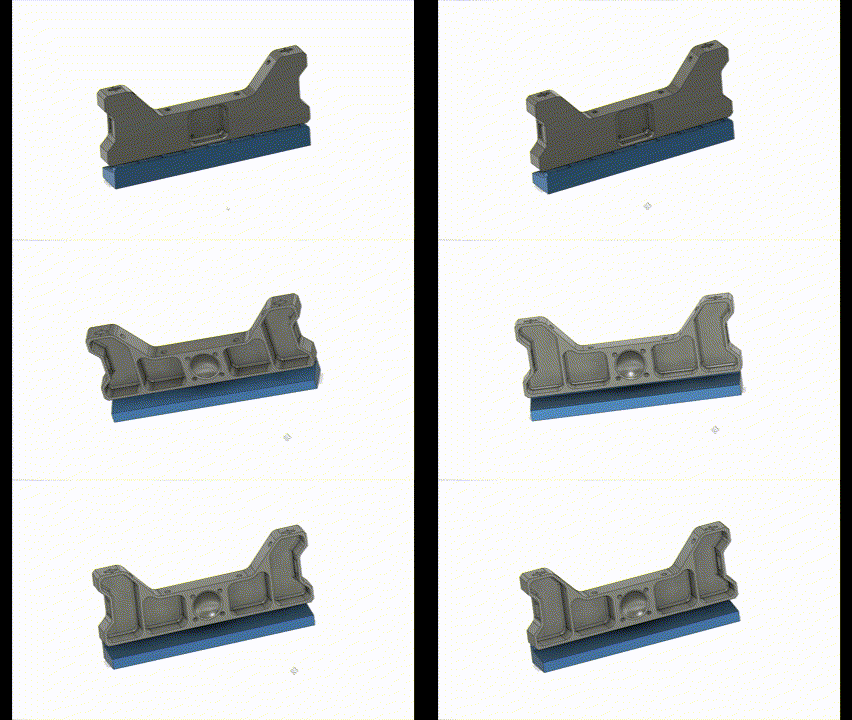
Straight edge tabs are my preferred way of breaking a part out in one single operation, although they are less universal as you are more restricted by part geometry.
With this design the tabs are evenly spaced across one straight edge of the part. It is critical that the part has no chamfers or radii along this edge, or this method will not work.
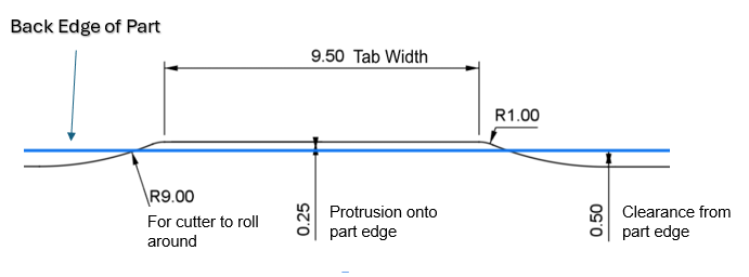
When designing the tabs (See Image 1), the main goal is spacing them correctly to support the part in its final machining stages. The tabs can either be smaller (Referring to tab width) with a higher quantity, or larger with a lower quantity. The tabs shown in Image C are 12mm wide with a total quantity of nine. Each tab must protrude 0.25mm onto the part face, with a 0.5mm gap in between.
Image: 1 - Example tab design
Critical Dimensions (Aluminium):
- 0.25mm Protrusion onto edge
- 0.50mm Clearance from edge
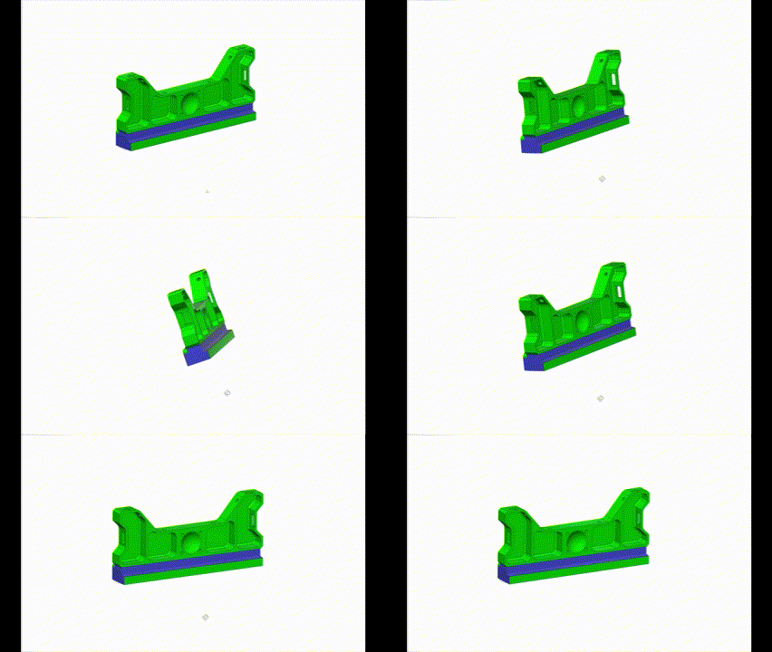
With the straight edge tab method, the order in which you remove the material is absolutely critical. It is obvious that if you were to remove all the material in one go, all rigidity would be lost before the part was finished, resulting most likely in nothing but a scrap part.
For this reason, as shown below in video E, the programmer must remove that material in stages, i.e. you would start by blanking off the gap underneath the part, and then rough out to that profile and finish all the external features.
Video: E - Stage 1 - Part still rigid, external finishing complete
Once you have achieved this you would remove most of the excess material left under the part leaving approx 5mm to retrain the rigidity, and then finish the larger portion of the back face, shown below in video F.
Video: F - Stage 2 - Reducing waste to 5mm thick, finishing large portion of back face
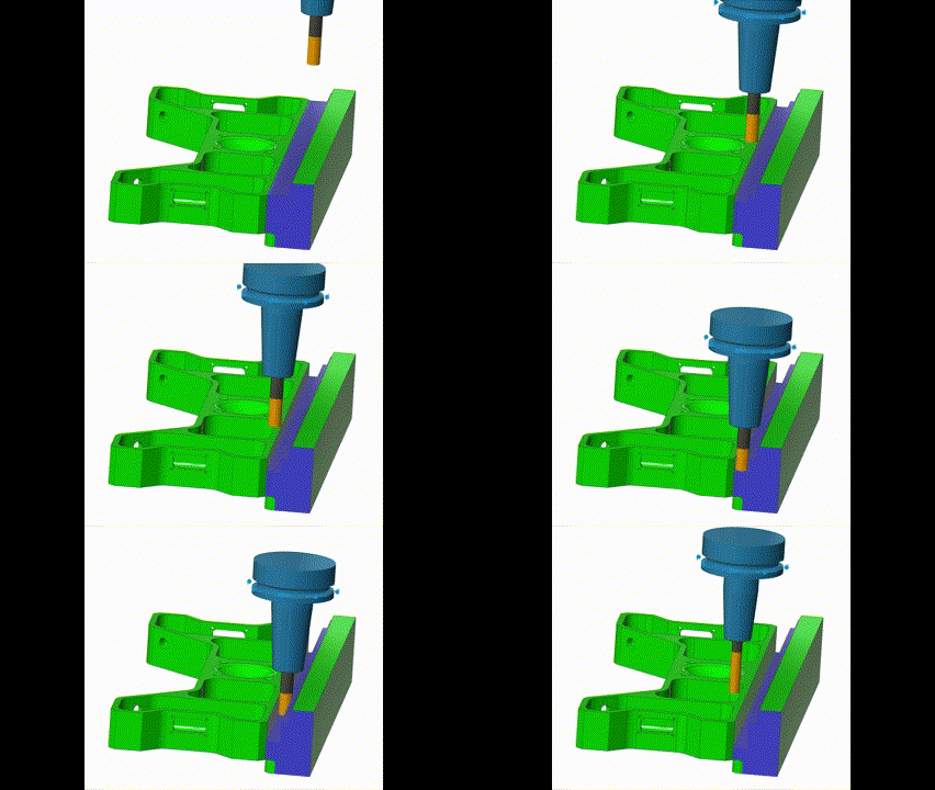
Finally, you would use the finishing endmill to wall finish down to approx 0.2mm past the bottom of the tabs, using a reduced Z increment (Between 0.5mm - 1.0mm depending on cutter diameter) until the part is held only by the 0.25mm tabs adjoined to the back edge of the part, shown below in video G.
Video: G - Stage 3 - Finishing endmill using reduced Z increments to break past bottom edge of part
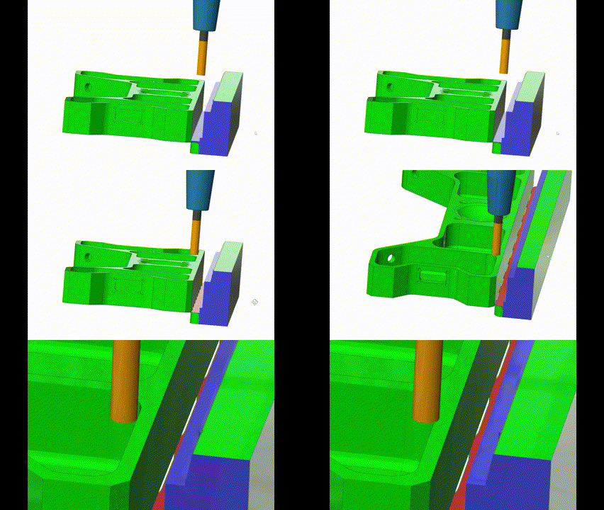
Note: Divide the Z increments evenly so that the endmill only takes one single finishing pass past the bottom edge of the part (creating gap between tabs ready for break-out), if the endmill takes another pass chatter will occur on the back face as rigidity is lost.
For more information on using straight edge tabs check out this video:Jay's Tips - How to avoid hand finishing when snapping out a part in one operation
So what is the better method when using the single operation break-out method?
Well, when you weigh up the pros and the cons of both traditional tags and straight edge tabs, it may be tempting to conclude that the traditional tag design is best. However, that’s not always the case! Traditional tags are by far more applicable to a wider range of parts, but, in most cases, they will require hand polishing.
Personally, I do not like to hand polish CNC parts, as I prefer my parts to have all faces machine finished. You may work in an industry where a little hand polishing is not an issue, and if that is that case then great: traditional tags are definitely something worth looking into, simply because of how universal they are.
Due to this hand polishing caveat, with traditional tags I will generally only break a part out in one operation if I can use the straight edge tab method so that I can achieve a fully machine finished part - with the only exception being one straight edge that will require a hand deburr. I do not consider deburring one edge by hand an issue unless I have a high volume production run.
If the part geometry does not allow the straight edge tab method, I will normally default back to a multi-operation machining process to 100% complete the part. including machine deburring.
Of course, programming these parts is another story - to accelerate that process, why not check out our CAM Assist AI solution?
For more information on the two break-out methods check out this video:Straight Edge Tabs vs Traditional Tags (youtube.com)


